Designing an ESP32 PCB for low power involves optimizing power rails, placing components strategically, and minimizing current leakage during sleep modes to extend battery life. This guide covers sleep mode fundamentals, PCB layout, power management, leakage reduction, and common mistakes to help you build battery-powered ESP32 devices with months of standby time.
How to Reduce ESP32 Power Consumption ?
To reduce ESP32 power consumption to under 10 µA in deep sleep:
- Use an ultra-low quiescent current LDO (<5 µA)
- Disable WiFi, Bluetooth, ADC, and unused peripherals
- Set all unused GPIOs to input with pull-down or high impedance
- Remove or switch off LEDs and sensors using load switches
- Optimize PCB layout with short power traces and a solid ground plane
With proper PCB design and firmware optimization, ESP32 deep sleep current can reach as low as 5–10 µA, and hibernation mode can go below 1 µA.
ESP32 Low Power Modes Overview
ESP32 offers three core sleep modes to balance power saving and wakeup speed, with drastically different current profiles.
Light Sleep
CPU stops, peripherals idle, RAM retained; typical current: 0.8–3 mA. Fast wakeup (microseconds), ideal for short idle periods.
Deep Sleep
CPUs & digital peripherals off; only RTC, ULP coprocessor, and RTC memory active. Current: 5–20 μA (optimized PCB can hit <10 μA).
Hibernation
Most internal circuits powered down; only external wakeup triggers work. Current: <1 μA, lowest power but longest wakeup latency.
ESP32 Sleep Modes Comparison
| Mode | Current Consumption | Wake-up Time | Active Components | Use Case |
|---|---|---|---|---|
| Light Sleep | 0.8–3 mA | < 1 ms | CPU paused, RAM retained | Short idle periods |
| Deep Sleep | 5–20 µA | ~100 ms | RTC, ULP, RTC memory | Battery-powered IoT |
| Hibernation | < 1 µA | > 100 ms | Minimal RTC | Ultra-long standby |
PCB Layout Strategies for Low Power
Poor layout can double or triple sleep current; follow these rules for minimal leakage.
Power Rail Partitioning
- Split digital core and RTC domain power rails to avoid cross-domain leakage
- Use star power routing from the battery or PMIC
- Keep power traces short, wide, and continuous
- Avoid splits in the ground plane
👉 Good power architecture can reduce leakage by up to 50%.
LED Indicator & Power Switch Layout
- Remove status LEDs in battery designs
- Or control LEDs via MOSFET load switch
- Place power switches close to battery
- Avoid unnecessary pull-up/down resistors
👉 LEDs are one of the most common hidden current drains.
Minimizing Power Leakage
Leakage often comes from PCB parasitics and unoptimized components.
- Shorten power traces to reduce parasitic effects
- Keep RF/high-speed signals away from RTC lines
- Place 0.1 µF decoupling caps within 1 mm of ESP32 pins
- Use 1–10 µF bulk capacitors
- Maintain a continuous ground plane
👉 Poor routing alone can increase sleep current by 2–10×.
Battery & Power Management
The regulator choice defines your baseline sleep current.
LDO vs DC-DC for Battery Operation
- LDO
- Simple and low noise
- Choose IQ < 5 µA
- DC-DC Buck
- Better efficiency under load
- Choose IQ < 20 µA
👉 For low-power IoT, quiescent current matters more than efficiency.
Voltage Monitoring & Load Management
- Add under-voltage lockout (UVLO)
- Use load switches to disconnect peripherals
- Route VBAT directly to RTC domain if possible
👉 Load switching can cut total sleep current by over 70%.
Recommended Low Power ESP32 Circuit Design
Key components:
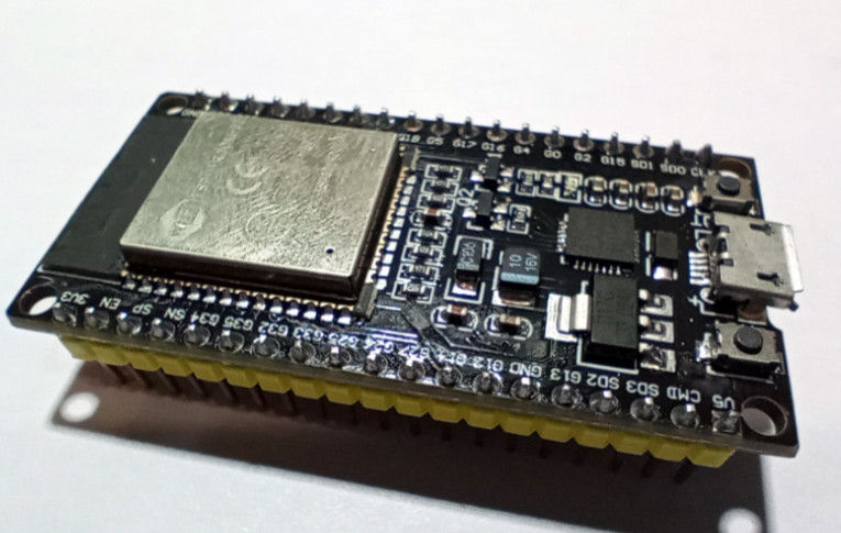
- ESP32 module (ESP32-WROOM-32)
- Ultra-low IQ LDO regulator (<5 µA)
- Load switch (for sensors and peripherals)
- Decoupling capacitors (0.1 µF + 10 µF)
Design tips:
- Use P-MOSFET to disconnect external modules
- Avoid direct LED connection to power rails
- Keep regulator close to ESP32
Software & GPIO Optimization
Hardware alone is not enough — firmware directly impacts sleep current.
- Disable WiFi, Bluetooth, ADC, DAC before sleep
- Set unused GPIOs to high-impedance or pull-down
- Use ULP coprocessor for periodic tasks
👉 Floating GPIOs can add 10–100 µA leakage.
Real-World Measurement Example
In a well-optimized ESP32 PCB design:
- Regulator: Ultra-low IQ LDO (1.5 µA)
- No status LEDs
- All GPIOs configured
- Sensors disconnected via load switch
Measured results:
- Deep sleep current: 7.8 µA
- Hibernation current: 0.9 µA
Comparison:
- Non-optimized board: >120 µA
- Cause: LED leakage + floating GPIOs
👉 Proper design can reduce current by over 90%.
Common Low Power PCB Mistakes
These errors are responsible for most high sleep-current failures.
Insufficient Decoupling
Capacitors placed too far from power pins cause instability
Unisolated High-Power Components
LEDs and sensors continue drawing current
Leakage from Poor Routing
Long traces and broken ground increase leakage
Floating GPIOs
Creates hidden internal current paths
Wrong Regulator Selection
High IQ regulators dominate power consumption
FAQ
How to reduce ESP32 sleep mode current on PCB?
- Use ultra-low-IQ regulators (<5 µA)
- Remove or switch off LEDs
- Optimize PCB layout
- Eliminate floating GPIOs
- Place decoupling caps close to pins
Why is my ESP32 deep sleep current too high?
Common causes include:
- Power LED still connected
- High quiescent current regulator
- Floating GPIO pins
- Sensors not disconnected
What is the lowest possible ESP32 current?
- Deep sleep: ~5 µA
- Hibernation: <1 µA
Does PCB layout affect ESP32 power consumption?
Yes. Poor layout can increase leakage by 2–10× due to:
- Long traces
- Ground discontinuity
- Parasitic capacitance
Summary
Achieving ultra-low power consumption on an ESP32 PCB requires a combination of:
- Proper sleep mode selection
- Optimized power architecture
- Tight PCB layout
- Correct firmware configuration
By separating power domains, minimizing leakage paths, using ultra-low-IQ regulators, and controlling peripherals and GPIOs correctly, you can reliably achieve:
- Deep sleep current <10 µA
- Hibernation current <1 µA
Most failures come from avoidable mistakes such as floating GPIOs, LEDs, poor layout, and high-IQ regulators.
With a well-designed system, ESP32 devices can run for months or even years on a small battery, making them ideal for:
- IoT sensors
- Wearables
- Remote monitoring systems
👉 Always measure sleep current early using a precision multimeter or power analyzer to validate your design.